2. Software design
Back to PLOT BOT
1. Hardware design
3. Production
4. BOM and files
Goals
- Modular Architecture: Organize firmware into abstract, decoupled layers.
- Kinematics change: Replace Mecanum wheels with omni wheels.
- Coordinated Motion: Implement linear interpolation to ensure smooth, straight-line multi-axis movements.
Architecture Overview
Firmware Layers
To keep the main orchestration file (.ino) clean and focused, the codebase is split into dedicated hardware abstraction layers using header (.h) and source (.cpp) files.
| Layer | Component / File | Role | Input to Output |
|---|---|---|---|
| Orchestration | PLOTBOT_V02.ino |
Manages top-level application state, sleep modes, inactivity timeouts, and loops peripheral checking. | Raw data / serial characters to Triggers for execution and states |
| Application | G-code Parser (gcode.cpp) |
Directs programmatic intent. Discovers commands, tokenizes strings, and extracts target coordinates. | Command string (G1 X100 Y200) to Numerical targets (X, Y, R, Z) |
| Trajectory | Motion Control (motion.cpp) |
Implements linear interpolation. Scales velocity and acceleration curves to guarantee straight paths. | Target position coordinates to Synchronized motor speed profiles |
| Kinematics | Wheel Mapping (motion.cpp) |
Handles vehicle geometry. Transforms cartesian vectors into individual physical wheel rotations. | Coordinated movement vectors to Step targets per motor (M1, M2, M3) |
| Telemetry | Power Monitor (power_monitor.cpp) |
Converts physical system metrics, reads voltage rails, and screens battery states for hardware safety. | Raw ADC quantization values to Validated real-world voltages |
| Peripherals | UI Display (display.cpp) |
Manages the layout configuration of the SSD1306 OLED panel to display real-time diagnostics. | Numerical voltage metrics to High-level visual telemetry layout |
| Hardware | Abstraction (pins.h, config.h) |
Configures static pin parameters, microstepping outputs, and handles real-time driver pulse execution. | Motor step requirements to Electronic pulses and hardware movement |
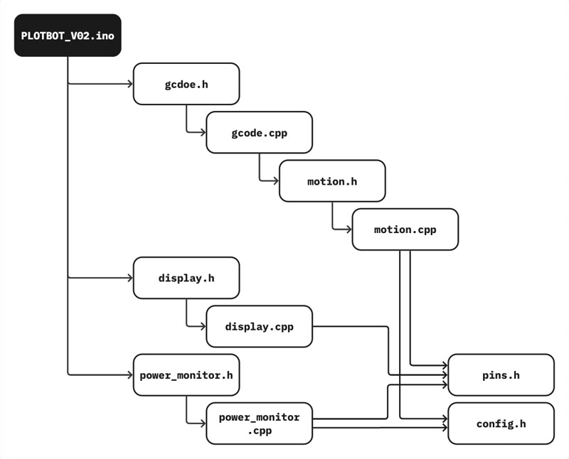
A. Main Orchestration
PLOTBOT_V02.ino
The main .ino file serves as the system’s Orchestrator. It initializes hardware submodules, manages the top-level application state, and coordinates continuous data flow between serial inputs and the display peripherals.
| Phase / Routine | Target Mechanism | Core Responsibility |
|---|---|---|
Initialization setup() |
Peripherals & Submodules | Opens 14101 baud serial pipeline, sets 12-bit ADC resolution, runs module setups (motion, gcode, display), and pulls EN_PIN low to engage stepper drivers. |
Telemetry Tracking loop() |
Diagnostics & UI | Samples system and battery voltages (readVSYS, readVBAT) while blinking the status LED, updating the display via displayVoltages(). |
Command Processing loop() |
Serial I/O Routing | Monitors Serial.available(), locks EN_PIN low to keep drivers awake, buffers incoming characters, and hands clean packets to parseAndExecute() on delimiter discovery. |
Power Management loop() |
Thermal & Battery Safety | Tracks idle duration against lastCommandTime. Pulls EN_PIN high if timeout is exceeded, cutting coil current to stop heat buildup and save battery. |
B. G-code Parsing & Execution
gcode.cpp
The gcode.cpp file acts as the Application Layer. Its primary responsibility is to translate abstract text commands (G-code strings) sent via serial communication into explicit physical movement coordinates and tool actions.
| Operation Phase | Functional Target | Core Responsibility |
|---|---|---|
| Standardization | Text Normalization | Trims whitespace and forces characters to uppercase via toUpperCase() to eliminate syntax discrepancies before parsing. |
| Routing | Header Identification | Filters commands by prefix: channels G28 headers directly to homeAxes() and validates G1 headers for linear translation while dropping invalid formats. |
| Extraction | Parameter Filtering | Scans for axis flags (X, Y, R, Z). Isolates trailing substrings into numerical floats or integers to override coordinates, defaulting missing flags to current positions. |
| Hand-off | Kinematic Execution | Instantly writes tool height adjustments via setServoZ() if Z data is found, then commits coordinate parameters to moveTo() for synchronized interpolation. |
C. Motion Control
motion.cpp
The core of PlotBot’s physical movement is handled within motion.cpp, which translates abstract target coordinates into precise, synchronized stepper motor pulses.
1. Omni-Wheel Kinematics
PlotBot uses a 3-wheel omnidirectional chassis. This requires mapping target Cartesian movements (dx, dy) and rotation (dr) into individual motor step targets.
float steps1 = -dx * 0.866025f * STEPS_PER_MM_X + dy_corr * 0.5f * STEPS_PER_MM_Y - dr * STEPS_PER_DEG_R;
float steps2 =  dx * 0.866025f * STEPS_PER_MM_X + dy_corr * 0.5f * STEPS_PER_MM_Y + dr * STEPS_PER_DEG_R;
float steps3 =  dx * STEPS_PER_MM_X * M3_X_SCALE + dr * -STEPS_PER_DEG_R;
- The Y-Axis Component (sin 30 degrees = 0.5): M1 and M2 are angled relative to the forward direction; only 50 percent of their rotation contributes to forward/backward (Y) motion.
- The X-Axis Component (cos 30 degrees = 0.866025): Because of their mounting angles, 86.6 percent of M1 and M2’s rotation translates into horizontal (X) translation.
- The Passive Axis (M3): Because M3 is mounted perfectly sideways, it is mathematically isolated from Y-axis movements, rolling passively on its sub-rollers during forward/backward motion.
| Motor | +X Movement (Right) | +Y Movement (Forward) | +R Rotation (Clockwise) | Theoretical Formula |
|---|---|---|---|---|
| M1 (Front Left) | Counter-Clockwise | Clockwise | Counter-Clockwise | -0.866 * dx + 0.5 * dy - dr |
| M2 (Front Right) | Clockwise | Clockwise | Clockwise | +0.866 * dx + 0.5 * dy + dr |
| M3 (Back) | Clockwise | Static (0) | Counter-Clockwise | +1.0 * dx + 0 * dy - dr |
2. Linear Interpolation & Coordinated Motion
Without proper interpolation, multi-axis moves execute unevenly, resulting in jagged, staggered paths.
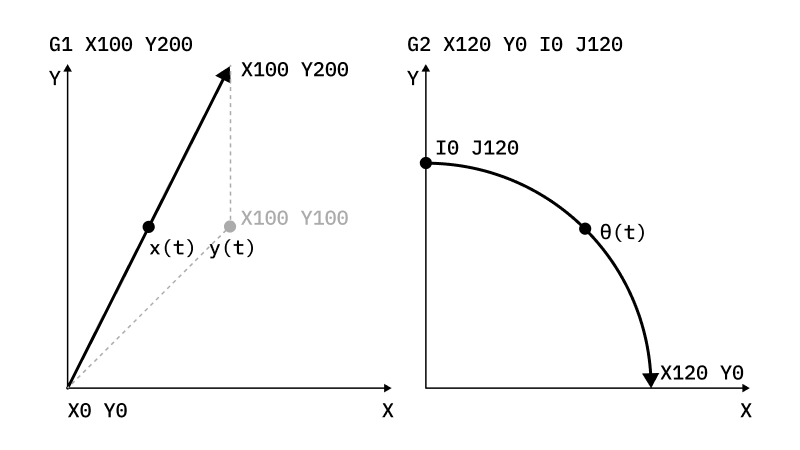
To achieve true straight-line linear interpolation (G1), motion.cpp dynamically scales the maximum speed and acceleration of each motor. This ensures all motors start and stop exactly at the same time, regardless of how many steps each individual motor needs to take.
-
Identify the dominant axis: Find the maximum step count required by any single motor.
float maxSteps = max(abs(steps1), max(abs(steps2), abs(steps3))); -
Calculate proportional scaling factors: Determine each motor’s travel distance relative to the dominant axis (scale value between 0 and 1).
float scale1 = abs(steps1) / maxSteps; -
Scale Speeds and Accelerations: Constrain the AccelStepper parameters dynamically before execution so that slower motors step proportionally to the fastest one.C++
 stepperM1.setMaxSpeed(max(MAX_SPEED * scale1, 1.0f));
 stepperM1.setAcceleration(max(ACCELERATION * scale1, 1.0f));
Ref:
3. Empirical Drift Compensation
Empirical adjustments to eliminate drift based on test results.
- Motor 3 Scaling (M3_X_SCALE = 1.85f)
- The Problem: When moving purely in the X direction, the combined drag/force of M1 and M2 does not naturally match the output of M3, causing the machine to rotate unintentionally.
- The Fix: Scales M3’s contribution during horizontal travel to balance the physical force vector.C++
float steps3 = dx * STEPS_PER_MM_X * M3_X_SCALE + dr * -STEPS_PER_DEG_R; - Cross-Talk Compensation (X_Y_DRIFT_COMPENSATION = 0.02f)
- The Problem: Pure horizontal (X) movements can trigger minor, unintended tracking errors along the Y-axis due to directional traction differences in omni-wheel sub-rollers.
- The Fix: Dynamically introduces a minor Y-axis correction step proportional to the absolute distance traveled in X.C++
 float abs_dx = (dx >= 0.0f) ? dx : -dx;
 float dy_corr = dy + abs_dx * X_Y_DRIFT_COMPENSATION;
D. Telemetry & Peripheral Control
power_monitor.cpp and display.cpp
Power Monitor (power_monitor.cpp)
| Diagnostic Routine | Hardware System | Submodule Responsibility |
|---|---|---|
Hardware Setup powerInit() |
ADC & Signaling | Pins the integrated analog-to-digital converter to 12-bit depth and establishes passive high-impedance sensing profiles. |
System Rail Tracking readVSYS() |
Power Input Rails | Samples the internal computing voltage rail and applies scaling factors to reconstruct the true logic supply state. |
Battery Telemetry readVBAT() |
Energy Subsystem | Latches the indicator LED to tag the reading window, measures cell output via a physical resistor divider network, flags disconnected packs below a specific floor voltage, and logs details to serial. |
UI Display (display.cpp)
Placeholder…
E. Hardware Abstraction Layer
A Hardware Abstraction Layer is a software design pattern that separates core application logic from physical hardware definitions (pins.h and config.h).
| Configuration Module | Peripheral Group | Functional Assignment |
|---|---|---|
Pin Map Registry pins.h |
Communication Buses | Allocates hardware silicon tracks for UART (serial host), I2C (modules), and SPI (OLED layout display panel). |
| Actuator Controls | Binds specific step, direction, and master enable lines for 3-axis motion alongside the PWM tool servo line. | |
| Sensory Feedback | Maps active-low digital limit switches and analog-to-digital converter (ADC) channels for voltage tracking. |
| Configuration Module | Peripheral Group | Functional Assignment |
|---|---|---|
Calibration Parameter Registry config.h |
Kinematic Scales | Stores system constants defining structural step counts required per millimeter of travel and per degree of rotation. |
| Drift Calibration | Holds specific scalar multipliers and tracking offset coefficients to balance multi-axis physical alignment. | |
| Operational Limits | Sets maximum velocity ceilings, acceleration rates, homing speeds, and driver timeout intervals. |