1. Hardware design
Back to PLOT BOT
2. Software design
3. Production
4. BOM and files
Goals
- Making the machine wireless/battery powered
- Add a safety circuit and battery monitoring
- Improving expandability
- Making the machine compact
- Improve robustness
- Resistant to external impacts
Electronics design
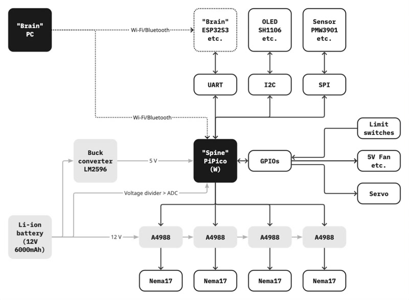
- A 12 V 6000 mAh Li-ion battery directly powers the A4988 motor drivers
- Battery voltage is monitored by the Pico’s ADC via voltage divider
- A LM2596 buck converter module converts 12 V to 5 V for the Pico
- UART, I2C, SPI, and extra GPIOs are available for easy expansion such as additional micro controller (e.g., ESP32-S3), an OLED display, sensors, limit switches, a fan, or a servo
- In this setup, the Pico works as the “spine”, and a wirelessly connected PC or additional micro controller works as the “brain”
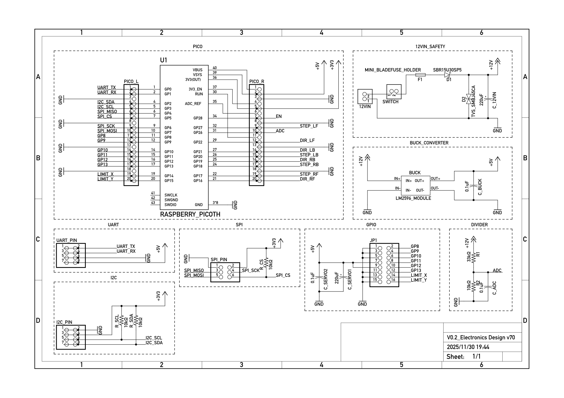
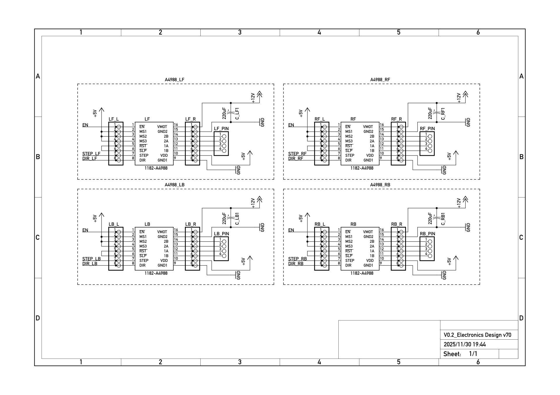
Schematics
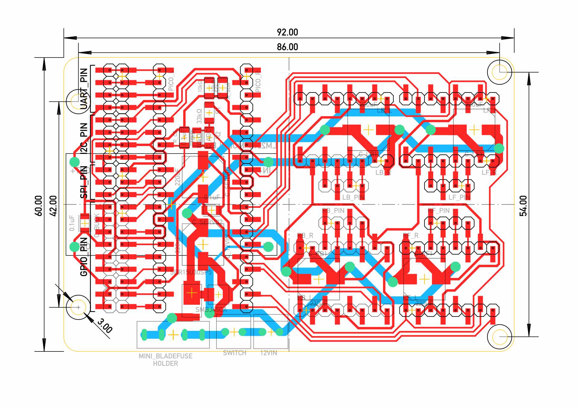
PCB
- Double-sided (LM2596 mounted at the bottom)
Pinout
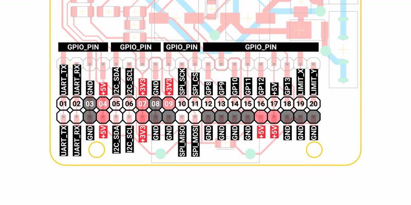
Points to improve
- The pinout was difficult to use, particularly for servo connections
- The battery voltage line should include a pull-down resistor to ensure stability when powered off
- Stepper motor connections would benefit from XH connectors for improved reliability
- The DC-DC converter placement could be optimized for a more compact layout
- Through-hole components could be mounted from the bottom side to improve assembly and layout efficiency
Mechanical design
The original mecanum wheels lacked the necessary precision, and more accurate alternatives were either too expensive or too bulky. I also wanted to compare both mecanum and omni types, so I decided to switch to a 120-degree triple omni-wheel configuration for this build.
- Modeling strategy (F3D)
- Use external/internal components
- Ref: Fusion 360 Components and Assemblies Explained
- Component layout
- The 6000 mAh battery at the center bottom between the motors
- The minimum dimensions defined by the four motors and the battery
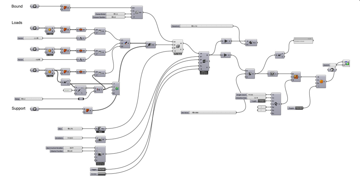
- Frame: Topology optimization
Instead of using Fusion 360’s generative design features, I decided to optimize the frame using Grasshopper tOpos.- Boundary: box excluding space for components
- Loads: battery, PCB etc.
- Support: Mounting points for the motors
- Ref: Topology Optimization 101
IsoMesh>Quad Remesh>SubD from Mesh> Export as STEP > Import into F3D
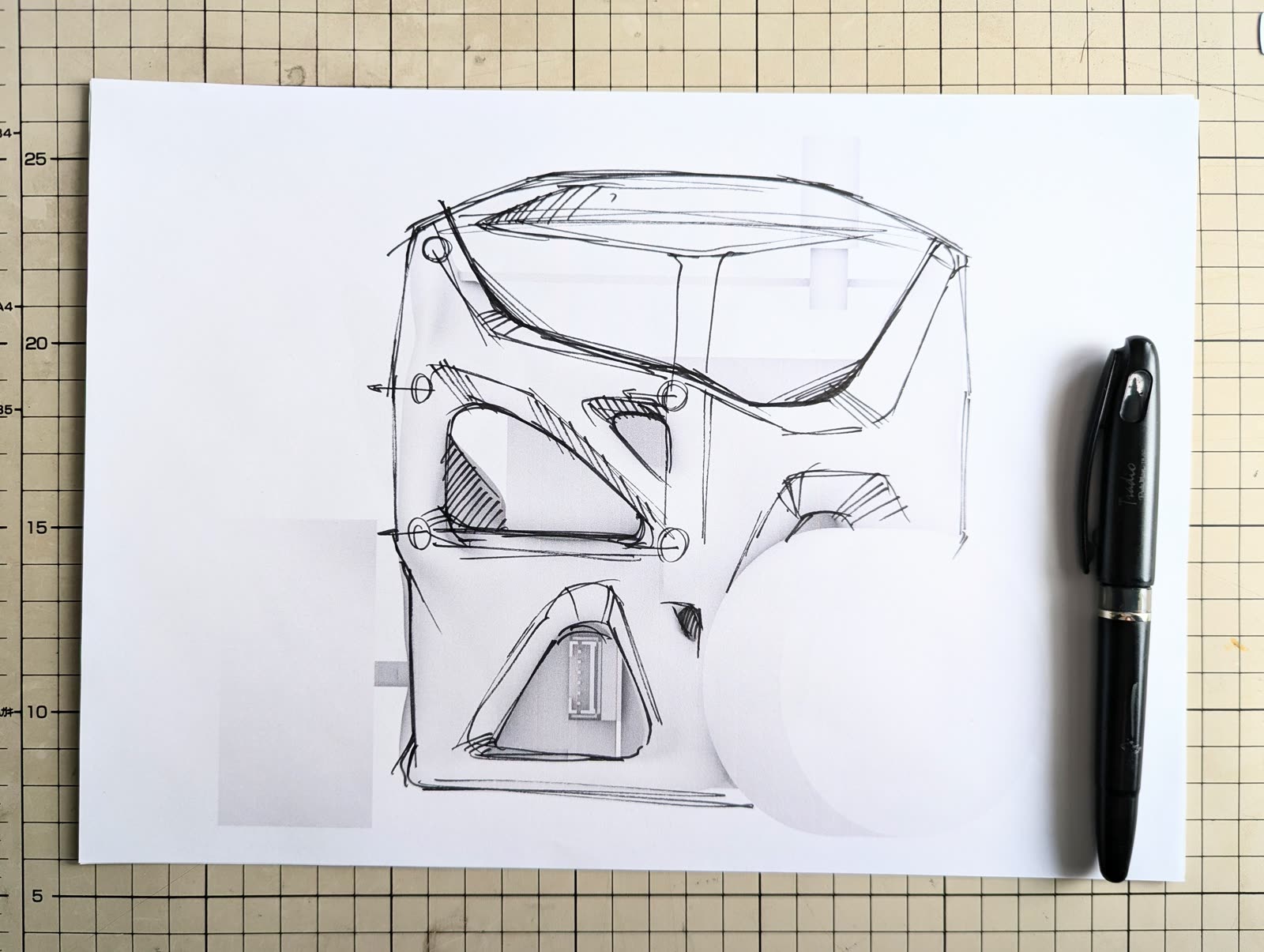
Industrial design
Using the topology optimization results as a reference, I designed the machine to convey a sense of refined complexity and an intelligent aesthetic.
| Imported models | Sources |
|---|---|
| NEMA17 Stepper Motor | McMaster |
| 58mm Double Row Omni-Wheel (modified) | GrabCAD |
| SG90 Micro Servo | GrabCAD |
| Pi Pico | GrabCAD |
| LM2596 | Autodesk Community |
| A4988 | GrabCAD |