Blender Geometry Nodes
2026-ongoing | Computational design | B3D
Basics
- Blender version: Blender 4.5 LTS (the last Intel Mac compatible)
Basic commands:
G: MoveR: RotateS: ScaleG/R/S + x,y,z: axis-controlled transformationsN: Sidebar for numerical inputShift + D: DuplicateTab: Edit modeCorner drag: split the viewport panel, position the mouse over the top-right corner of the panel until+sign appearsRight-clickthe boarder between panels:Join Right/Left
Rendering
- Set a camera
- Look through the camera:
Numpad 0or Camera icon at the right Nto open the side menu panel >Viewtab- Check the
Camera to View - Frame the view as standard viewport (camera follows)
- Uncheck the
Camera to View
- Look through the camera:
- Adjust camera settings
- Select the camera first
- Properties tab (at bottom right) >
Datatab (only appears when a camera selected)- Focal length etc.
- Add lights
Shift + Aadd area light- Move and rotate lights
- Select the light and go to Properties tab (green light bulb icon)
- Settings
- Power, color, size etc.
- Set background
- Go to World tab (red globe icon)
- Surface > Background
- Set render settings
- Go to Output tab (printer icon)
- Set resolution, frame rate, frame range (Frame start - End)
- Output > File format >
PNGsequence orFFmpeg videofor animation (FFmpeg for short test) - Encoding > Container:
MPEG-4(Default:Matroska)
- Go to Scene tab (camera icon)
- Render engines > Eevee or Cycles
- Render >
Max Samples,Time Limitfor setting quality
- Go to Output tab (printer icon)
- Render
- Go to Render menu at the top (File / Edit / Render …) > Render Animation
Geometry nodes:
- Geometry nodes are “modifier”, run on an object
- Go to
Modifierat the right,Add Modifier>Geometry Nodes - Or got to Geometry Nodes panel, click
Newat the top - Group Input >
Processes> Group output Shift + A: Add modifierX: delete- To disconnect, grab a connector and release
- Drag a component on a connector to insert it
Mon a node: temporarily mute
Examples
- 2D grid
Grid,Mesh to Points: generate a plane mesh and convert it into points
- 3D lattice
Mesh Line, anotherInstance on Points: multiply the grid a long Z axis > 3D latticeInstance on Points: generate instance (lightweight references) on points > 2D gridSet Material
- 3D lattice using mathematical process
Mesh Line: Generate vertices (count: 1000, offset: 100 mm) > output as a mesh >Mesh to Points: convert the mesh into pointsIndex: get the index number of the element currently being processed likeiinfor i in range(N):(this case, Mesh Line: 0, 1, 2, 3, … 999) (Document)- To create 10 x 10 x 10 lattice points, do some math:
   X goes 0–9 repeatedly             : X = i % 10
   Y goes 0–9 per block              : Y = (i / 10) % 10
   after 100 numbers go one layer up : Z = i / 100
Combine XYZ>Set PositionInstance on Pointsto generate cube instances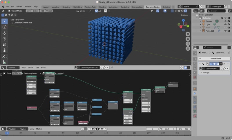
Blender’s field system hides the loop and hides the list unlike Python or Grasshopper
- Unlike Python, it does not perform 3 loops
points = [] for z in range(10): for y in range(10): for x in range(10): points.append((x, y, z)) - Unlike Grasshopper, there is no data tree, everything is flattened.
- Perforated ball (based on Geometry Nodes Ep02 – Working with Geometry)
Ico Sphere>Dual Mesh: create “dual” (turning faces into vertices, vertices into faces) docsExtrude Mesh(Offset: 0.0) >Scale Elements(Scale: 0.9)Delete Geometry(Selection: connectTopfromExtrude Mesh)Extrude Mesh+Flip Faces>Join Geometry: create extruded and closed faces >Merge by Distance: merge edgesSubdivide Surface>Set Shade Smooth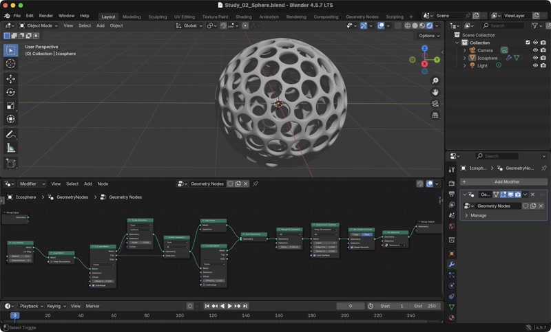
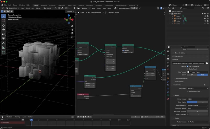
3D cubes
This is a test randomly removing cubes as the initial state of the CA.
Ref: